Aeronautical Navigation Systems - Airway Beacon
An airway beacon was a rotating light assembly mounted atop a tower. These were once used extensively in the United States for visual navigation by airplane pilots along a specified airway corridor. Approximately 1,500 airway beacons were constructed to guide pilots from city to city, covering 18,000 miles (29,000 km). Most of the beacons are gone, but The State of Montana continues to maintain several as navigation aids in mountainous terrain. One beacon is preserved for historical purposes in Saint Paul, Minnesota at the Indian Mounds Park on a bluff overlooking the Mississippi River. Recently, the beacon at Grants, New Mexico was restored for historic preservation, using original items found at other nearby sites.
A large concrete slab, in the shape of an arrow, was located near the base of each beacon. Many of these arrows remain today, some of which are visible from satellite pictures, even in urban settings.
Light characteristics
An airway beacon has two distinct light characteristics: A revolving narrow white light beam about 5 degrees wide in azimuth and a set of fixed colored course lights of about 15 degrees width.
White rotating beacon
The rotating beacon features a 24 inch (610 mm) parabolic mirror and a 110-volt, 1 kilowatt lamp. spinning at 6 rpm, creating a quick 1/10 second flash every 10 seconds. In clear weather they could be seen for 40 miles (64 km). Montana took steps to modernize their beacons encasing newer light systems in clear domes.
Red or green course lights
Just below the white beacon, a set of red or green course lights point along each airway route. Red lights denote an airway beacon between landing fields while green denotes a beacon adjacent or upon a landing field. These course lights flash a Morse code letter identifying the beacon to the pilot. Each beacon is identified with a sequential number along the airway, and flash the red or green course lights with the Morse code ID of one of 10 letters: W, U, V, H, R, K, D, B, G or M. The letters represent the digits of 1 through 10 (W = 1, ..., M = 10). The course lights turn on for 0.5 second for a dot, 1.5 second for a dash with a 0.5 second between each dot or dash. A pause of 1.5 seconds separates each letter.
To help remember the letters and their sequence number, pilots memorized the following: "When Undertaking Very Hard Routes, Keep Direction By Good Methods." The beacons are depicted on navigation charts along with their number and Morse code pattern. For example, beacon number 15 would have a code digit of 5 (the units digit), hence the letter R, and Morse code: "dit dah dit"
Reference
wikipedia.org/wiki/Airway_beacon
Labels
airway beaconsbeacon lights of historyaerospace jobsaeronautical engineering jobsunmanned aerial vehiclesaircraft maintenanceaircraft navigation lightsbeacon lights of history
Farming Principle: Deep Soil Preparation
Looking at GB as a three-legged stool, deep soil preparation is one of the legs. Deep soil preparation builds soil and soil structure by loosening the soil to a depth of 24 inches (60 cm). Ideal soil structure has both pore space for air and water to move freely and soil particles that hold together nicely.
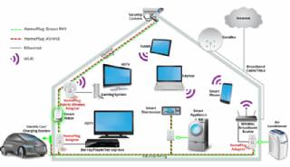
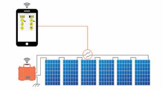
Smart Home Ecosystem - Smart Home Automation - Smart Home Security - Smart Home Technology
The outer-most level corresponds to the individual devices and sensors that consumers interact with. Several candidates are vying for the role of a leader introducing smart home services to the mass market.
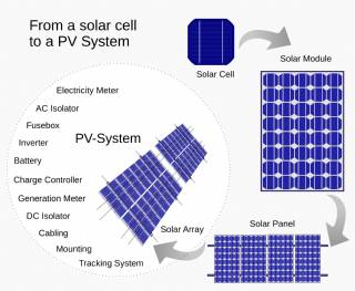
Solar Energy Systems - Solar Modules - Solar Electric System Design - Solar Power
The heart of a photovoltaic system is the solar module. Many photovoltaic cells are wired together by the manufacturer to produce a solar module. When installed at a site, solar modules are wired together in series to form strings. Strings of modules are connected in parallel to form an array.
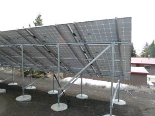
Solar Energy Systems - Array Mounting Racks - Solar Ray - Solar Panel - PV Racks and Mounts
Arrays are most commonly mounted on roofs or on steel poles set in concrete. In certain applications, they may be mounted at ground level or on building walls. Solar modules can also be mounted to serve as part or all of a shade structure such as a patio cover. On roof-mounted systems, the PV array is typically mounted on fixed racks, parallel to t
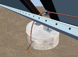
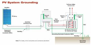
Solar Energy Systems - Grounding Equipment
Grounding equipment provides a well-defined, low-resistance path from your system to the ground to protect your system from current surges from lightning strikes or equipment malfunctions. Grounding also stabilizes voltages and provides a common reference point. The grounding harness is usually located on the roof.
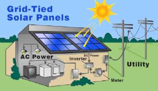
Solar Energy Systems - Solar Inverter - Solar Panel Inverter
Most grid-connected inverters can be installed outdoors, while most off-grid inverters are not weatherproof. There are essentially two types of grid-interactive inverters: those designed for use with batteries and those designed for a system without batteries.
Solar Energy Systems - Solar Disconnects
Automatic and manual safety disconnects protect the wiring and components from power surges and other equipment malfunctions. They also ensure the system can be safely shut down and system components can be removed for maintenance and repair.
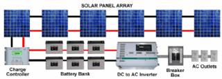
Solar Energy Systems - Solar Battery Bank
Batteries store direct current electrical energy for later use. This energy storage comes at a cost, however, since batteries reduce the efficiency and output of the PV system, typically by about 10 percent for lead-acid batteries. Batteries also increase the complexity and cost of the system.
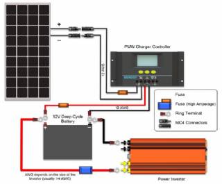
Solar Energy Systems - Solar Charge Controller
A charge controller, sometimes referred to as a photovoltaic controller or battery charger, is only necessary in systems with battery back-up. The primary function of a charge controller is to prevent overcharging of the batteries. Most also include a lowvoltage disconnect that prevents over-discharging batteries. In addition, charge controllers pr
Solar Energy Systems - The NEC and PV Systems
Solar PV systems must be installed in accordance with Article 690 of the National Electric Code, which specifically deals with PV systems, as well as several other articles of the NEC that pertain to electrical systems in general. When there is a conflict between NEC 690 and any other article, NEC 690 takes precedence due to the unique nature of PV