12-bit Computers CDC 160 Series
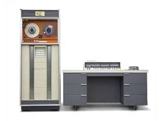
The CDC 160 series is a series of discontinued minicomputers built by Control Data Corporation. The CDC 160 and CDC 160-A are 12-bit minicomputers built from 1960 to 1965; the CDC 160G is a 13-bit minicomputer, with an extended version of the CDC 160-A instruction set, and a compatibility mode in which it did not use the 13th bit. The 160 was designed by Seymour Cray - reportedly over a long three-day weekend[citation needed]. It fit into the desk where its operator sat.
The 160 architecture uses ones' complement arithmetic with end-around carry.
NCR joint-marketed the 160-A under its own name for several years in the 1960s.
The CDC 160-A was a simple piece of hardware, and yet provided a variety of features which were scaled-down capabilities found only on larger systems. It was therefore an ideal platform for introducing neophyte programmers to the sophisticated concepts of low-level Input/output (I/O) and interrupt systems.
All 160 systems had a paper-tape reader, and a punch, and most had an IBM Electric typewriter modified to act as a computer terminal. Memory on the 160 was 4096 12-bit words. The instruction set was small and RISC-like. The CPU had a 12-bit ones' complement accumulator but no multiply or divide. There was a full complement of instructions and several addressing modes. Indirect addressing was almost as good as index registers. The instruction set supported both relative (to the current P register) and absolute. The original instruction set did not have a subroutine call instruction and could only address one bank of memory.
In the 160-A model, a "return jump" and a memory bank-switch instruction was added. Return-jump allowed simple subroutine calls and bank switching allowed other 4K banks of memory to be addressed, albeit clumsily, up to a total of 32,768 words.[2] The extra memory was expensive and had to live in a separate box as large as the 160 itself. The 160-A model could also accept a multiply/divide unit, which was another large and expensive peripheral box.
In the 160 and 160-A, the memory cycle time was 6.4 microseconds. An add took two cycles. The average instruction took 15 microseconds, for a processing rate of 67,000 instructions per second.
The 160G model extended the registers and memory words to 13 bits; in G mode, all 13 bits were used, while in A mode, only the lower 12 bits were used, for binary compatibility with the 160-A. The 160G added some instructions, including built-in multiply and divide instructions, and some additional addressing modes.
Low-level I/O allowed control of devices, interfacing for determining device status, and for reading and writing data as either single bytes, or as blocks. I/O could be completed to a register, or to memory, or via a direct memory access (DMA) channel. The distinction between these I/O types was that regular I/O would 'hang' the CPU until the I/O operation completed, but DMA I/O allowed the CPU to proceed with instruction execution concurrently with the data transfer. The interrupt system was purely based on IO, meaning that all interrupts were generated externally. Interrupts were introduced to neophytes as being the alert mechanism by which a program could be informed that a previously initiated DMA I/O operation was completed.
Reference:
wikipedia.org/wiki/CDC_160_series
Labels
12 bit adcadc convertera to d converter16 bit adcadc resolution12 bit dac12 bit displaybit resolutionadc chipFarming Principle: Deep Soil Preparation
Looking at GB as a three-legged stool, deep soil preparation is one of the legs. Deep soil preparation builds soil and soil structure by loosening the soil to a depth of 24 inches (60 cm). Ideal soil structure has both pore space for air and water to move freely and soil particles that hold together nicely.
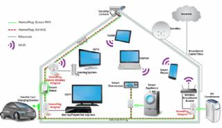
Smart Home Ecosystem - Smart Home Automation - Smart Home Security - Smart Home Technology
The outer-most level corresponds to the individual devices and sensors that consumers interact with. Several candidates are vying for the role of a leader introducing smart home services to the mass market.
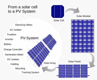
Solar Energy Systems - Solar Modules - Solar Electric System Design - Solar Power
The heart of a photovoltaic system is the solar module. Many photovoltaic cells are wired together by the manufacturer to produce a solar module. When installed at a site, solar modules are wired together in series to form strings. Strings of modules are connected in parallel to form an array.
Solar Energy Systems - Array Mounting Racks - Solar Ray - Solar Panel - PV Racks and Mounts
Arrays are most commonly mounted on roofs or on steel poles set in concrete. In certain applications, they may be mounted at ground level or on building walls. Solar modules can also be mounted to serve as part or all of a shade structure such as a patio cover. On roof-mounted systems, the PV array is typically mounted on fixed racks, parallel to t
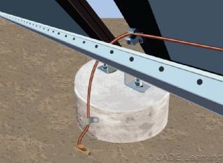
Solar Energy Systems - Grounding Equipment
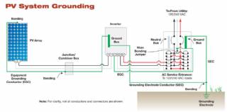
Grounding equipment provides a well-defined, low-resistance path from your system to the ground to protect your system from current surges from lightning strikes or equipment malfunctions. Grounding also stabilizes voltages and provides a common reference point. The grounding harness is usually located on the roof.
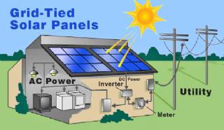
Solar Energy Systems - Solar Inverter - Solar Panel Inverter
Most grid-connected inverters can be installed outdoors, while most off-grid inverters are not weatherproof. There are essentially two types of grid-interactive inverters: those designed for use with batteries and those designed for a system without batteries.
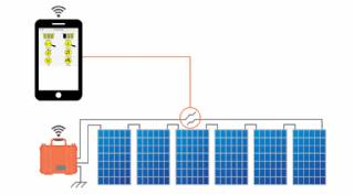
Solar Energy Systems - Solar Disconnects
Automatic and manual safety disconnects protect the wiring and components from power surges and other equipment malfunctions. They also ensure the system can be safely shut down and system components can be removed for maintenance and repair.
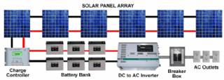
Solar Energy Systems - Solar Battery Bank
Batteries store direct current electrical energy for later use. This energy storage comes at a cost, however, since batteries reduce the efficiency and output of the PV system, typically by about 10 percent for lead-acid batteries. Batteries also increase the complexity and cost of the system.
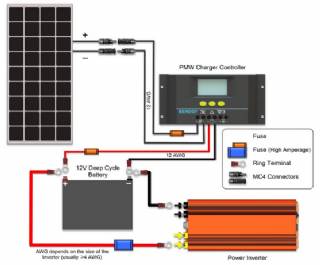
Solar Energy Systems - Solar Charge Controller
A charge controller, sometimes referred to as a photovoltaic controller or battery charger, is only necessary in systems with battery back-up. The primary function of a charge controller is to prevent overcharging of the batteries. Most also include a lowvoltage disconnect that prevents over-discharging batteries. In addition, charge controllers pr
Solar Energy Systems - The NEC and PV Systems
Solar PV systems must be installed in accordance with Article 690 of the National Electric Code, which specifically deals with PV systems, as well as several other articles of the NEC that pertain to electrical systems in general. When there is a conflict between NEC 690 and any other article, NEC 690 takes precedence due to the unique nature of PV