Ideal Wind Power Calculations
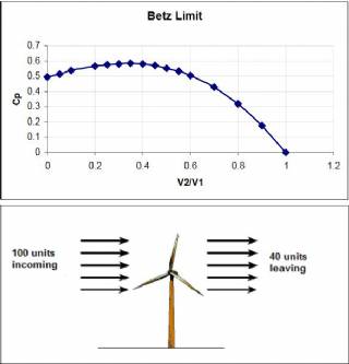
The value of the ideal power is limited by what is know as Betz coefficient with a value of Cp = 0.59 as the highest possible conversion efficiency possible.
In practice, most wind turbines have efficiencies well below 0.5, depending on the type, design and operational conditions. In the operational output range, wind power generated increases with wind speed cubed. In other words, at a wind speed of 5 m/s, the power output is proportional with 5 cubed = 125, whereas at a wind speed of 10 m/s, the power output is proportional to 1000. This shows that doubling the speed from 5 to 10 m/s resulted in a power increase of 8 folds. This highlights the importance of location when it comes to install wind turbines. The effect of the rotor diameter affect the power output in a square manner, i.e, doubling the rotor diameter results in increasing the power output by four times.
On the other hand, since power generated is related to wind speed by a cubic ratio. That means if your turbine is rated at producing 1KW at 12m/s then it will produce 125W at 6m/s and 15W at 3m/s.
Theory of Wind Turbines
A windmill extracts power from the wind by slowing down the wind. At stand still, the rotor obviously
produces no power, and at very high rotational speeds the air is more or less blocked by the rotor, and
again no power is produced.
The Power produced (Pkin) by the wind turbine is the net kinetic energy change across the wind turbine (from initial air velocity of V1 to a turbine exit air velocity of V2) is given.
The mass flow rate of wind is given by the continuity equation as the product of density, area swept by the turbine rotor and the approach air velocity.
The theoretical maximum fraction of the power in the wind which could be extracted by an ideal windmill
is, therefore the fraction 0.5925 is called the
Betz Coefficient
. Because of aerodynamic imperfections in
any practical machine and of mechanical loses, the power extracted is less than that calculated above. Figure 3.7 demonstrates the effect of wind turbine design implications on the resulting power that can be harnessed from the incoming wind. Efficient wind turbines depend on the production of that optimum speed ratio giving the maximum or near the maximum power possible.
Equation 14 clearly shows that:
-The power is proportional to the density (p) of the air which varies slightly with altitude and temperature
-The power is proportional to the area (A) swept by the blades and thus to the square of the radius (R) of the rotor; and
-the power varies with the cube of the wind speed (V3). This means that the power increases eightfold if the wind speed is doubled. Hence, one has to pay particular attention in site selection.
Distinction between rated and actual power output of the turbine
The world's largest wind turbine generator has a rotor blade diameter of 126 metres and is located on offshore, at sea-level and so we know the air density is 1.2 kg/m3. The turbine is rated at 5MW in 30mph (14m/s) winds,
Rotor Swept area A= 1262)/4 = 12469 m2
Wind Power = 0.5 x A x x V3
= 0.5x12469x 1.2 x (14)3 = 20.5 MW
Why is the power of the wind (20MW) so much larger than the rated power of the turbine generator (5MW)?
The answer lies in the fact that the Betz limit and inefficiencies in the system seriously absorbs over 60% of the apparent power. There are two further factors to be considered when estimating the power output from a turbine, the first is the mechanical transmission and the second is the generator’s efficiency, both of which are less than unity, hence the real power is proportionately less than the ideal value.
The capacity factor, Cf. Assuming a 5 kW wind turbine generates annually 10 MWh, if that same installation had run – theoretically – 24 hours a day and 365 days a year at full load, it would have generated 43.8 MWh. The capacity factor (Cf) is 10/43.8 = 0.23. Typical values for Cf between 0.2 and
0.4 in the united kingdom, depending on the exact location.
Labels
wind power calculationrenewable energywind generatorwind turbine generatorwind power for homeswind turbine costvertical wind turbinewind turbine for home
Farming Principle: Deep Soil Preparation
Looking at GB as a three-legged stool, deep soil preparation is one of the legs. Deep soil preparation builds soil and soil structure by loosening the soil to a depth of 24 inches (60 cm). Ideal soil structure has both pore space for air and water to move freely and soil particles that hold together nicely.
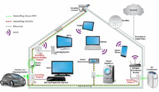
Smart Home Ecosystem - Smart Home Automation - Smart Home Security - Smart Home Technology
The outer-most level corresponds to the individual devices and sensors that consumers interact with. Several candidates are vying for the role of a leader introducing smart home services to the mass market.
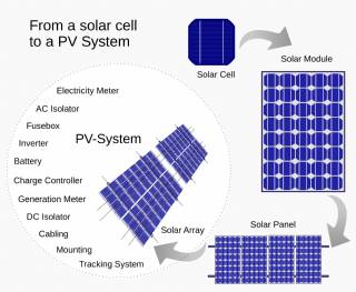
Solar Energy Systems - Solar Modules - Solar Electric System Design - Solar Power
The heart of a photovoltaic system is the solar module. Many photovoltaic cells are wired together by the manufacturer to produce a solar module. When installed at a site, solar modules are wired together in series to form strings. Strings of modules are connected in parallel to form an array.
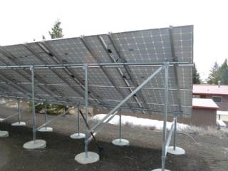
Solar Energy Systems - Array Mounting Racks - Solar Ray - Solar Panel - PV Racks and Mounts
Arrays are most commonly mounted on roofs or on steel poles set in concrete. In certain applications, they may be mounted at ground level or on building walls. Solar modules can also be mounted to serve as part or all of a shade structure such as a patio cover. On roof-mounted systems, the PV array is typically mounted on fixed racks, parallel to t
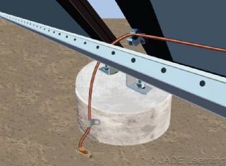
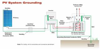
Solar Energy Systems - Grounding Equipment
Grounding equipment provides a well-defined, low-resistance path from your system to the ground to protect your system from current surges from lightning strikes or equipment malfunctions. Grounding also stabilizes voltages and provides a common reference point. The grounding harness is usually located on the roof.
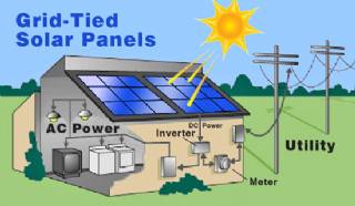
Solar Energy Systems - Solar Inverter - Solar Panel Inverter
Most grid-connected inverters can be installed outdoors, while most off-grid inverters are not weatherproof. There are essentially two types of grid-interactive inverters: those designed for use with batteries and those designed for a system without batteries.
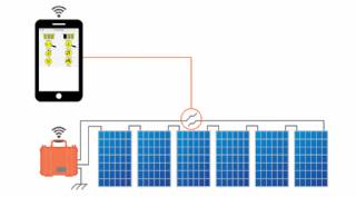
Solar Energy Systems - Solar Disconnects
Automatic and manual safety disconnects protect the wiring and components from power surges and other equipment malfunctions. They also ensure the system can be safely shut down and system components can be removed for maintenance and repair.
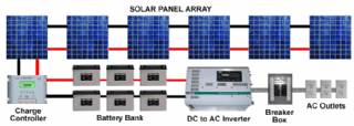
Solar Energy Systems - Solar Battery Bank
Batteries store direct current electrical energy for later use. This energy storage comes at a cost, however, since batteries reduce the efficiency and output of the PV system, typically by about 10 percent for lead-acid batteries. Batteries also increase the complexity and cost of the system.
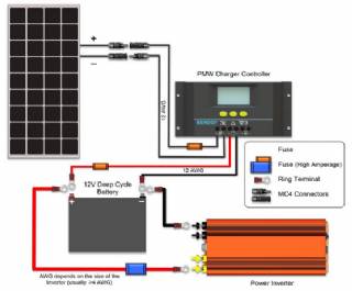
Solar Energy Systems - Solar Charge Controller
A charge controller, sometimes referred to as a photovoltaic controller or battery charger, is only necessary in systems with battery back-up. The primary function of a charge controller is to prevent overcharging of the batteries. Most also include a lowvoltage disconnect that prevents over-discharging batteries. In addition, charge controllers pr
Solar Energy Systems - The NEC and PV Systems
Solar PV systems must be installed in accordance with Article 690 of the National Electric Code, which specifically deals with PV systems, as well as several other articles of the NEC that pertain to electrical systems in general. When there is a conflict between NEC 690 and any other article, NEC 690 takes precedence due to the unique nature of PV